About Vibration Control
For a detailed understanding of the causes of vibration and how our VIBRAPLANE systems can help, click below.
All buildings vibrate… activities of people, machinery, heating and ventilation systems, and nearby truck or rail traffic cause all sorts of vibrations. These vibrations, although acceptable to occupants, cannot be tolerated by equipment used in research, precision manufacturing, inspection, and quality control.
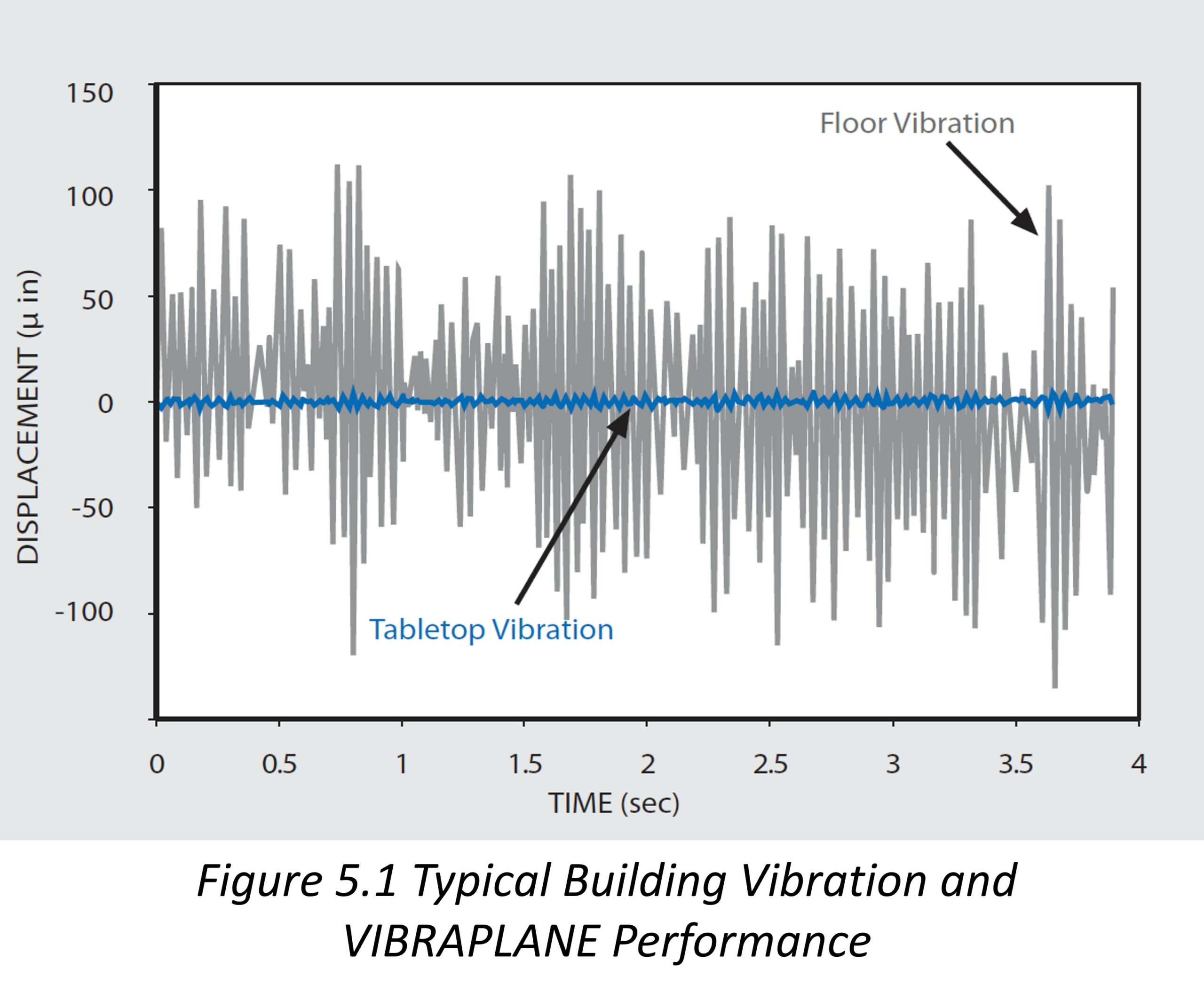
Ambient vibration levels in buildings, laboratories, and cleanrooms vary widely. Figure 5.1 shows a typical time sample of a severe building vibration environment. The vibration is a random amplitude and random frequency disturbance. In this environment, sensitive electromechanical equipment will experience a variety of problems such as structural damage and excessive signal noise. Optical equipment will experience low frequency jitter and high frequency image blur and line thickening. The short term effects are inconsistent and unreliable performance. The long term effects are excessive wear, maintenance and fatigue failures.
In order to protect sensitive instruments and equipment from faulty operation or failure this vibration must be significantly reduced. This can be efficiently accomplished by using a KSI VIBRAPLANE ISOLATION system either by the end user at the point of installation; or integral to the equipment by OEM designers at a point where the vibration sensitive components are installed.
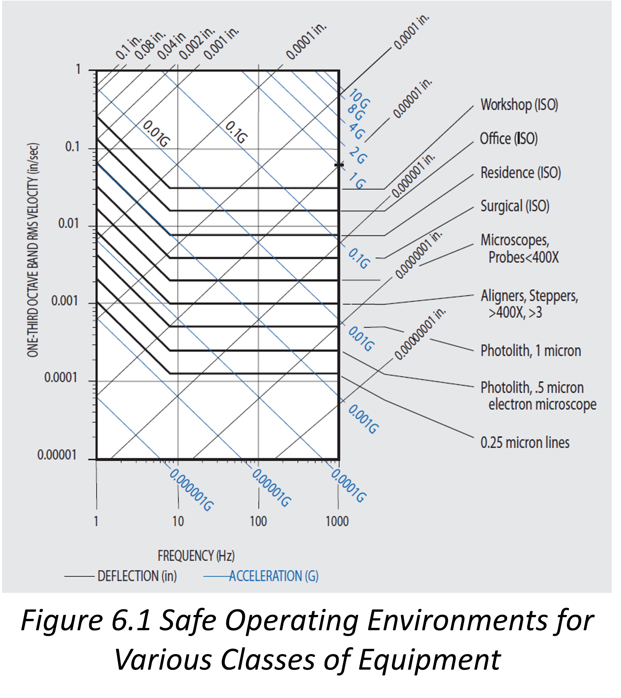
A four-coordinate vibration nomograph has been superimposed in Figure 6.1. The inclined coordinates of the nomograph conveniently allow direct reading of rms vibration amplitude as a function of frequency in units deflection, in., velocity, in./sec, or acceleration, G in multiples of gravity, g.
The data are very conservative and represent subjective opinions as to the onset of operational problems such as signal noise or optical blurring. They don’t represent structural damage or failure. Further, the data are rms 1/3 octave band width (23%) filter analyses. Adjustment is necessary if comparing to data with different measurement bandwidths.
- In new buildings or facilities, KSI recommends, and can provide, onsite vibration surveys to define the environment. Results that indicate vibration amplitudes at frequencies exceeding the applicable equipment specification criteria require isolation.
- If new equipment is being installed in an existing facility where other equipment is performing successfully with vibration isolation, then isolation should be continued and applied for the new equipment. It is substantially more cost- and time-effective to continue a successful practice rather than experiment with a new, unknown situation.
- If new equipment is being installed in an existing facility where no other equipment is isolated, you may continue the practice of no isolation. However, new equipment designs generally embody more precision and are therefore more sensitive than the older equipment. We recommend isolation in this situation as a fail-safe solution, especially if time is a critical factor for going online.
Look at the application. Due to the large variety of instrument components and designs, equipment sensitivity to vibration is a subject of continuing research. So the question of “How much vibration is acceptable” is not precisely known. Equipment manufacturers typically strive to achieve specified performance tolerances in a benign or noncritical development laboratory environment. It is the end user’s responsibility to provide a “safe operating vibration environment”at the point of installation. There are limited available data on
the ability of various classes of equipment to withstand vibration. These data have been compiled from various surveys and are presented in Figure 6.1 to represent proposed safe operational vibration levels for a variety of sensitive instruments. Each equipment line represents an acceptable envelope of rms vibration amplitude vs frequency which is not to be exceeded. The “allowable” vibration envelopes in Figure 6.1 have been proposed by various engineering committees for standardization by the International Standards Organizations (ISO) to supplement their existing standards.
Simple Isolation System
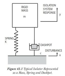
For analysis it is customary to idealize structures, objects and isolation systems as simple mass-spring-damper systems as shown in Figure 42.1. The mass m is infinitely rigid. The spring is weightless and its stiffness is K lbs/in. The damper, or dashpot, is weightless and its damping coefficient is c lbs/in./sec.
Natural Frequency
All objects vibrate when subjected to impact, noise or vibration. When the stimulation is removed, the object will experience periodic sinusoidal oscillations or free vibration at a frequency which is called its Natural Frequency fn in (Hz cycles/sec). With little or no damping, the Natural Frequency of a simple system such as Figure 42.1 is defined as follows:
f n = 3.13 (K/W) 1/2 (1)
Where mass m = W/g, and
g = acceleration of gravity = 386 in/sec 2
Damping
In a simple system, Damping serves as an energy dissipation “dashpot” to limit the magnification of system response. Actual Damping c is conveniently referenced to
Critical Damping c c which is the value of damping at which a system will not oscillate when disturbed from equilibrium. Critical Damping is related to the system mass and natural frequency, as follows:
c c = 78.96 (mf n 2 ) (2)
Forced Vibration, Transmissibility and Resonance
If the simple system in Figure 42.1 is subjected to Forced Vibration at frequency f , and sinusoidal foundation motion at amplitude x , the absolute value of the mass response amplitude y expressed as a ratio |y/x| , also known as Transmissibility T , will be as follows:

(3)
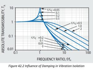
Figure 42.2 is plotted as a function of forcing frequency ratio f/f n and critical damping ratio c/c c . If external vibration is applied at a frequency which coincides with the Natural Frequency; i.e., (f/f n )= 1 , a condition of Resonance occurs. At resonance the system will experience very large potentially damaging magnification of the disturbing forces.
The maximum Transmissibility T max at resonance is commonly referred to as the Q of the system and is approximately related to Critical Damping, as follows:
T max = Q = 1/2 c c (4)
Dashpot or damping force is proportional to velocity. The forces due to high damping are desirable at resonance to oppose damaging magnification, but less desirable at high frequencies because this tends to negate vibration attenuation. This is evident in Equation (3).
Isolation Efficiency
Isolation Efficiency E in percent transmission is related to Transmissibility as:
E = 100 (1-T)% (5)
and is the percentage of the vibration isolated from the payload. It should be observed in Equation (3) and Figure 42.2, that in order to achieve the best isolation efficiency the isolator’s natural frequency should be very low. This is the basic philosophy of VIBRAPLANE Isolation.
Center of Gravity (cg)
The Center of Gravity is the point in an object where an external applied force produces displacement but no rotation. Typically the center of gravity will be located near the largest concentration of mass in the object and may be located by computation or experimental means. Equipment cg height and geometry are very important for considerations of stability and rocking when using soft supports to achieve vibration isolation. For best stable results, KSI recommends the cg height should not exceed 25% of the shortest span between supports.
Air Spring Stiffness and Natural Frequency
VIBRAPLANE isolation systems utilize the properties of compressed air to provide the uniquely low stiffness properties essential for the high efficiency broad frequency band isolation essential for high technology equipment. The Air Spring Stiffness K in lbs/in. is a function of absolute pressure P in psi, area A in sq. in., and volume V in cu. in., as follows:
K = PA 2 / V (6)
Combining Equations (1) and (6), the simple Air System Natural Frequency is:
f A = 3.13 (A / V) 1/2 (7)
It is basic to note in Equation (7) that increasing the air volume of the air spring results in a lower system natural frequency which is necessary for high isolation efficiently.
For end user applications, KSI manufactures complete lines of active-air and passive-air
mounts, platforms and tables, with load capacities from 200 lbs to 20,000 lbs per unit isolator. Standard or custom design table and platform configurations can be provided for research applications involving special assemblies of elements which are inherently vibration sensitive, such as probers, mask aligners, microscopes and the like.
For OEM applications, KSI manufactures unit active-air vibration isolators which are readily integrated into equipment to protect platforms and trays holding vibration sensitive elements. This is a cost-effective and space saving approach to achieve vibration control by process equipment manufacturers. When an equipment design is fixed and an integrated internal isolation system is not feasible, KSI can furnish a custom designed external isolation table or platform to provide the desired vibration environment protection.
We have performed all the necessary calculations, and relying on over thirty years of applied vibration control experience, offer the end-user point of installation pre-engineered, all-purpose, low frequency, vibration-free tables and platforms for tabletop and floor mounted equipment. For the OEM, KSI offers unit active air mounts in capacities and dimensions suitable for custom integration with internal system components and structures.
NOTE: For “Point of Design” vibration control, equipment designers should include attention to mass, stiffness and damping. For best results, KSI recommends that moving parts be lightweight, rigid and damped. Stationary parts should be heavy, rigid and damped. Sensitive elements are best placed together on a rigid platform inside the equipment console for grouped isolation. Whatever your design entails, KSI can help by providing custom fit vibration protection for all the sensitive components.
VIBRAPLANE Airmount Isolation Is Better
Conventional isolators are constructed using metal springs or rubber blocks. They have low internal damping, and tend to be effective only at frequencies near 10 Hz. Also, they provide almost no isolation at frequencies above 30 Hz because of “harmonic standing waves” occurring at sonic velocities in the metal or rubber.

The VIBRAPLANE design concept is shown in Figure 43.1. This design eliminates the metal springs or rubber blocks used in conventional isolator designs. The VIBRAPLANE utilizes a frictionless rolling diaphragm air seal to support a load carrying piston in conjunction with dual air chambers as the spring and damping medium. The air spring stiffness is a function of the combined air volume of the dual chambers. This conveniently provides the required very low stiffness to obtain the desired very low natural frequency necessary for high efficiency isolation. “Harmonic standing waves” cannot occur in the VIBRAPLANE System due to its dual air chamber internal damping design.
VIBRAPLANE Systems are Mobile
Since current and future building vibration requirements are uncertain, the safest, most cost-effective concept of vibration control in high technology facilities is vibration isolation of individual pieces of sensitive equipment at the point of installation. For both OEM and end user installations, VIBRAPLANE high performance systems provide vibration control independent of building construction. Unlike concrete inertia blocks or fixed support piers, VIBRAPLANE isolation systems are relatively compact and mobile, and may be easily moved or changed as future needs develop. The alternative, modifying buildings and internal structures, is costly and permanent with little or no margin for future requirements.
Our vibration surveys indicate that most building vibrations are complex, and may be characterized as a broadband random vibration spectrum with multiple superimposed strong discrete “tonal” frequencies. The broadband random vibration spectrum extends from 8 to 200 Hz. The multiple discrete tonal frequencies tend to occur between 8 to 80 Hz and are caused by motors, generators, blowers, pulleys, and gears, etc. The observed vibrations are mostly vertical, with horizontal vibrations averaging about 25% to 30% of the vertical. The frequency spectrum is essentially invariant, however discrete frequency amplitudes can vary by several orders of magnitude depending on the location and distance from the source of the disturbance.
Regardless of location, the above generalizations establish an 8 to 200 Hz frequency spectrum of concern for selecting vibration control to avoid damaging environmental frequencies which may coincide with equipment natural frequencies. KSI’s standard VIBRAPLANE vibration isolation systems are designed with a low 1 to 2 Hz natural frequency that will attenuate all potentially damaging vibration amplitudes in the 8 to 200 Hz environment spectrum.
Better Damping
The VIBRAPLANE utilizes a unique proprietary VARIFLO™ orifice design for flow control between air chambers, and therefore, better damping control is realized both high and low amplitudes and frequencies. This design ensures an even air flow at all amplitudes without choking, thereby maintaining the effectiveness of both (airspring) chamber volumes.
It can be seen in the schematic representation of Figure 43.1, that VARIFLO damping incorporates a “filtering” spring. This contrasts with vibrations the conventional isolator model of Figure 42.1 where the damper is direct coupled to the mass and causes a loss of isolation at high frequencies as shown in Figure 42.2. The VARIFLO damping (air) spring effectively decouples the damper at high frequencies and therefore no isolation is lost where high damping forces would tend to reduce efficiency in a conventional isolator.
Zero Friction
The VIBRAPLANE design uses a thin wall frictionless rolling diaphragm to support the (airspring) piston. This unique design prevents friction locking, which is a principle cause of loss of isolation for low frequency, micro-inch disturbances in conventional
Isolators.
![]()
VIBRAPLANE Transmissibility
The dual chamber design of the VIBRAPLANE produces a unique optimization of its vibration Transmissibility performance. See Figure 45.1. At low frequencies the air volume in both air chambers is effective, resulting in large air volume and a soft low natural frequency system. This is represented by the “left” branch of the Transmissibility curve. At high frequencies, the orifice gradually restricts the air flow and eventually only the small chamber is effective with a resulting stiffening of the system. This action is represented by the “right” branch of the Transmissibility curve. KSI’s proprietary orifice design is amplitude sensitive and configured to produce the “optimum” transmissibility bounded by the left and right branches. VIBRAPLANE thus affords the ideal conditions of maximum damping at resonance and minimum damping at high frequencies for better isolation than possible, using conventional isolation systems.
Active-Air Leveling
VIBRAPLANE Active-Air leveling provides leveling compensation and a wide load range. By utilizing a compressed air source and our proprietary VIBRALEVEL Air Servo Valves, air is fed into or bled from the (airsprings) to maintain a preset “zero deflection” level and compensate for load changes.
Horizontal Vibration Control
Horizontal vibrations in buildings average 25% to 30% of the vertical and are usually
less critical. Nevertheless, the VIBRAPLANE System includes the Kinematic Horizontal
Isolation Piston to provide isolation for any vibration environment regardless of direction.
The piston is internally constructed with rubber-in-shear elements that simultaneously translate and rock in a low frequency coupled response action to horizontal inputs. KSI BaseMate Platforms use an onmi-directional low frequency pendulum system to eliminate horizontal vibrations. Early on, KSI recognized precise system leveling is essential for proper horizontal vibration isolation, and was the first to introduce mechanical leveling feet on all workstations. This assures the maximum efficiency of our zero friction design. These leveling feet serve to equalize piston extension and prevent rubbing friction due to frame tilt.
Structural Damping
The structural damping used by Kinetic Systems eliminates the “ringing” caused by resonances in frame, table, and platform structures external to the VIBRAPLANE airspring suspension system. All structures experience resonance no matter how stiff or massive. Damping augmentation is the most efficient means to dissipate vibration energy. KSI’s engineering staff conducts continuing research and development of new and improved damping technologies which are incorporated into the production of all VIBRAPLANE systems. We use viscoelastic damping laminations and “tuned absorbers” on solid, composite, and honeycomb tables and platforms. In addition, frame structures are bolted through viscoelastic laminations.