Horizontal vs. Vertical Vibration Isolation: Lessons from the Lab
Vibration in laboratories is never one-dimensional. Floors move in six degrees of freedom with three translations and three rotations, and instruments respond differently to motion in each axis. While vertical motion (Z) often dominates below a few hertz, horizontal motion (X/Y and rocking) can degrade imaging and precision measurements at surprisingly low amplitudes, especially on upper floors or long-span structures.
Understanding how vertical and horizontal vibration affect sensitive equipment and how isolation systems manage those motions is key to achieving consistent data. Companies like Kinetic Systems, as a long-standing U.S. manufacturer of vibration isolation equipment, have refined these principles across decades of engineering. Our products are frequently used in research and industrial facilities as case studies for how to balance vertical and horizontal isolation effectively.
Why Direction Matters
It’s tempting to think of vibration as purely vertical. After all, people picture floors “bouncing.” But real-world lab data consistently show that horizontal motion is often the larger problem.
- For SEMs (Scanning Electron Microscopes): lateral floor motion shifts the electron column relative to the sample, producing image drift or blur even when vertical vibration meets VC criteria.
- For AFMs (Atomic Force Microscopes): vertical motion translates to height noise, but horizontal drift creates false topography, corrupting repeat measurements.
- For optical microscopes: above ~100× magnification, horizontal blur dominates; at lower magnifications, vertical focus variation is more noticeable.
- For CMMs (Coordinate Measuring Machines): all six axes matter equally. Rocking and horizontal translation often dominate repeatability errors.
Vertical vibration affects focus; horizontal vibration affects spatial accuracy. The relative importance of each axis depends on your instrument, your floor structure, and your isolation system’s mechanical design.
How Labs Quantify and Interpret Vibration
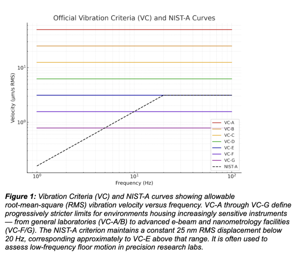
The most widely used benchmarks are the Vibration Criteria (VC) curves and the NIST-A criterion:
- VC Curves (VC-A through VC-G): These define one-third-octave RMS velocity limits from ~1–80 Hz, applied per axis. VC-D/VC-E are common in high-end labs; VC-F/VC-G are used for e-beam or nanometrology tools.
- NIST-A: Holds 25 nm RMS displacement from 1–20 Hz and roughly aligns with VC-E above that range.
Figure 1
Many labs make the mistake of averaging results across axes. A site might meet VC-E vertically but exceed VC-C horizontally, which means a gap large enough to visibly degrade imaging. Always compare each axis individually using one-third-octave RMS velocity data.
Sources of Horizontal and Vertical Vibration
- Human Activity: Footfall frequencies typically lie between 1.5 and 2.5 Hz. Modern long-span floors amplify this laterally, especially on upper stories.
- Building Systems: HVAC fans, pumps, and elevators operate at frequencies between 10 and 60 Hz. These often excite rocking modes in sensitive benches.
- External Influences: Nearby rail or traffic frequently produces strong horizontal components that dominate low-frequency vibration spectra.
- Structural Response: Rigid ground floors transmit vertical motion; flexible upper floors magnify lateral and torsional motion.
A vibration survey that includes all three axes (vertical and two horizontal) is the only reliable way to characterize these patterns.
How Isolation Systems Behave
Different isolation systems address the axes differently. Kinetic Systems’ catalog provides a clear illustration of this engineering balance.
Pneumatic Air Systems
Air-spring isolators, such as those used in Kinetic Systems’ VibraPlane and 9100 Series Workstations, perform exceptionally well above their natural frequency (typically ~1–2 Hz vertically, ~1.5–2 Hz horizontally). They can reduce transmitted vibration by more than 90 % above ~5 Hz. However, near resonance, they can amplify motion, especially at low frequencies produced by walking or building sway.
Mechanical Negative-Stiffness Systems
These use internal flexures and spring elements to reach vertical natural frequencies below 1 Hz and horizontal frequencies near 1–1.5 Hz. They are entirely passive and require no air or power. Such designs are particularly valuable for AFMs, interferometers, or optical metrology, where both vertical and horizontal stability at sub-hertz levels are critical.
Hybrid Cradle Platforms
For large, floor-mounted instruments, Kinetic Systems’ 9300 platforms combine pneumatic vertical isolation with a mechanical pendulum cradle for horizontal control. The result is balanced low-frequency isolation across all six degrees of freedom. This hybrid approach is especially effective for upper-floor installations and environments with dominant horizontal vibration in the 1–5 Hz range.
Matching the System to the Instrument
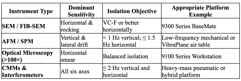
The design goal is not simply “less vibration;” it’s directional control. The correct platform depends on which axes dominate your instrument’s error budget.
Verification and Testing
Isolation effectiveness should always be validated through data and instrument performance:
- Pre-installation survey: Tri-axial vibration data (vertical + two horizontals), expressed in one-third-octave RMS velocity.
- Post-installation measurement: Repeat measurements on the isolated surface, not just the floor.
- Performance verification: Run the instrument’s diagnostic tests (SEM grid imaging, AFM noise floor, interferometer phase stability) to ensure environmental improvement translates into tool performance.
Kinetic Systems’ technical guides (linked below) provide procedures for air level calibration, load balancing, and maintenance to ensure the system performs to spec over time.
Case Insights: Direction Matters
- SEM Lab on the Third Floor:
- A microscopy suite met VC-D vertically but exceeded VC-C horizontally, leading to image drift. A hybrid isolation platform with low horizontal natural frequency corrected the issue without significant structural modification.
- AFM in a Shared Space:
- An AFM on a pneumatic table showed lateral drift despite acceptable vertical vibration. Switching to a sub-hertz passive isolator stabilized both axes, improving repeatability.
- Optical Bench Near HVAC Systems:
- A VibraPlane workstation with additional damping balanced both axes, maintaining focus and image sharpness despite nearby mechanical noise.
Each example underscores a core principle: isolation is never just about “stiffness;” it’s about frequency, direction, and mechanical coupling.
Common Missteps
- Assuming vertical vibration is the only issue. Horizontal motion can be equally or more destructive.
- Ignoring rocking modes. Uneven weight distribution or soft legs introduce torsional resonance.
- Overreliance on mass. Heavy slabs without compliant isolation can amplify low-frequency energy.
- Averaging vibration data. Axis-specific exceedances matter far more than composite numbers.
A well-designed isolation system is not just a table. It’s a dynamic filter. The difference between a pneumatic air-spring, a negative-stiffness flexure, and a hybrid cradle design lies in how each filters motion along each axis.
The engineering philosophy behind Kinetic Systems’ 9100, VibraPlane, and 9300 Series platforms illustrates this principle in practice. Pneumatic systems excel vertically; cradle and flexure systems extend that stability horizontally. The most successful installations combine accurate vibration data, direction-aware specification, and verification at the instrument level.
Ultimately, horizontal and vertical isolation are not competing priorities. They are two halves of a single engineering problem: ensuring your instruments see the world as still as possible.
Further Reading
Standards and Technical References:
- ANSI/ASHRAE 2008 Design Guide 11: Floor Vibration Due to Human Activity
- Vibration Criteria (VC) Curves – Colin Gordon Associates
- NIST-A Low-Frequency Criterion Overview
- Shin et al., “Vibration Control of Scanning Electron Microscopes,” Sensors (MDPI, 2020)
Kinetic Systems Technical Resources:
- Kinetic Systems 9100 Series Workstation User Guide (PDF)
- Kinetic Systems 9300 / BaseMate Isolation Platforms
- Kinetic Systems VibraPlane Overview
- Kinetic Systems Optical Tables & Breadboards
- Kinetic Systems Company Overview
comments
comments for this post are closed