About Optical Tables
What You Need to Know About Optical Tables
VIBRAPLANE Vibration Isolation Protects the Critical Subsystems of Large Equipment
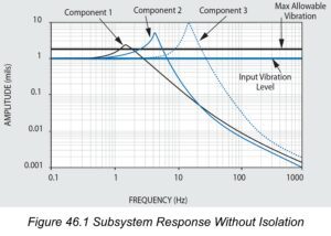
All complex assemblies include components with natural frequencies that are critical because they exist in the generalized 8 to 200 Hz environmental spectrum.
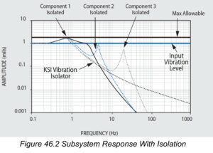
For illustration, Figure 46.1 shows the Transmissibility and resonant responses of three components in typical equipment. The resonant responses, or Q’s of these components exceed the allowable level, which is set at Q=1.75 for this example. Figure 46.2 shows the responses of the same components above, after the introduction of isolation at 1 Hz. The roll off isolator transmissibility acts to reduce the input to each of the three critical components illustrated. Now without altering the design of each component, their respective resonant responses are all below the allowable limit, and no failure will occur.
KSI Optical Tables… Better Built Through Better Design
At KSI, we’ve taken all the guesswork out of selecting optical tables and vibration control equipment. We have developed pre-engineered rigid and high natural frequency honeycomb optical tables, breadboards, and modular rigid supports (upgradeable to vibration isolators) to provide you with cost-effective solutions for any vibration environments you encounter. The choice is simple. For precision applications in severe or unknown vibration environments, we recommend highly damped honeycomb optical tables such as our 5300 Series and Active-Air vibration isolation systems. For normal or moderate environments we offer economical, broadband damped tables such as our 5200 Series or 5100 Series with Isolators or our Modular Rigid Supports.

Understanding Optical Table Specifications
At present there is no single accepted standard practice for comparison of optical tables from different manufacturers. This accounts for much of the unnecessary complexity in technical performance specifications introduced by different makers.
At KSI, we want you to be aware of the important difference between reality and specification hype. For example – flatness, stiffness, weight, static deflection, dynamic compliance, natural frequency, and damping are real properties of any optical table, and these are directly measurable by standard instruments and techniques. However, some manufacturers use theoretical estimates of intangible performance parameters which cannot be verified. For optical table selection and comparison, real measured data and test results can never be replaced by theoretical computed estimates based on idealized assumptions and unproven hypotheses.
Consider the Basics When Selecting and Specifying Optical Tables
There is so much technical jargon and unnecessarily complicated static and dynamic deflection concepts being used to sell optical tables and vibration isolation equipment that it’s easy to become confused and distracted from what you really need to know. We would like you to review the following basics so you can feel confident when selecting an optical table or isolation system for your application.
Natural Frequency
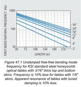
Optical tables should have a high natural frequency (preferably above 90 Hz) to avoid coincidence with prominent low frequency sinusoidal building vibrations typically occurring between 6 and 60 Hz. At KSI, we provide one piece tables in popular sizes up to 6 feet (1.83m) by 16 feet (4.88m) whose lowest natural frequency is 90 Hz or better to protect you from resonance with building vibrations. You can see this in our natural frequency graph in Figure 47.1. If the (length/width) ratio of the table is equal or greater than 1.33 the lowest frequency mode will be free-free bending, otherwise the lowest mode will be free-free twisting. For custom applications we can manufacture large tables with special tooling or by splicing one or more tables together. These will have lower natural frequencies which may be extrapolated from Figure 47.1.
Static Deflection
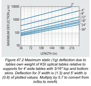
Optical tables should be stiff to minimize relative deflection, or sag, between supports due to their own weight. High stiffness in our tables and breadboards is insured by our proprietary damped rigid epoxy, and is not compromised by plastic or viscoelastic laminations. The high stiffness of our tables is confirmed by their high natural frequencies in Figure 47.1 and the corresponding very small static deflections shown in Figure 47.2. The maximum static (1g) deflection of KSI tables relative to their supports has been tested and conforms to simple beam deflection theory. It should also be noted that the tables’ static deflections are significantly less than their flatness tolerances.
Deflection Due to Equipment Load
In addition to minimizing static deflection, the high stiffness of our tables minimizes relative deflection due to weight of components and equipment installed on the table. If you assume that the installed equipment is uniformly distributed across the table, then the added table deflection due to the equipment is determined simply by multiplying the deflection from Figure 47.2 by the (equipment/table) weight ratio. If you are using heavy equipment, we recommend that you repeat this deflection computation with different table lengths and thicknesses until you obtain an acceptably low value, say 10%, of the precision required by your application.
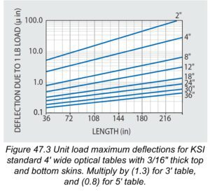
Unit Load Deflection
The maximum relative deflection due to a one-pound concentrated load centered on the table should be minimal and is presented in Figure 47.3. As is the case with our table static weight deflection tests, results show that unit load deflections also conform closely with simple beam deflection theory. To calculate the deflections due to higher magnitude concentrated loads at the center, simply multiply the unit load values in Figure 47.3 by the higher load value. For example, if the deflection due to a 250 lb load is desired, multiply the graph value by 250 for the selected table size.
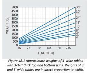
Optical Table Weight
Figure 48.1 presents the approximate weights for 48″ wide 5300 Series tables of various standard thicknesses. The weights of other corresponding tables of different width and skin thickness may be estimated by multiplying the values in Figure 48.1 by the ratios of (actual width/48″) or (actual skin thickness/ .180″) as appropriate. Our steel honeycomb optical tables are inherently structurally efficient and weigh substantially less than a solid steel or granite equivalent flat surface plate. Nevertheless, a certain amount of weight is desirable for stability and resistance to vibratory forces. Thickness and length govern the table weight. Two rules of thumb are: (1) the table should weigh between 2.5 and 5 times the mounted equipment; and (2) the minimum table thickness should be between 6% and 10% of the length. Use these rules to define the minimum weight of your table selection. For example, for precision applications the minimum recommended standard thickness of a 10′ long table should be 8″ or 12″ thick.
Static and Dynamic Deflection and Compliance
In optical tables it is customary to quantify dynamic deflection in terms of Compliance, which is simply the deflection response to a unit force. In static or steady state conditions, Compliance is easily identified as “inverse” stiffness, or flexibility in engineering units of deflection per unit force.
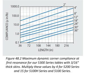
The Unit Load Deflections in Figure 47.3 can be regarded as a graph of Static Compliance values at the centerpoints of the tables presented. In contrast, Dynamic Compliance is the deflection response due to a unit vibratory force. Hence vibration frequency, table resonance and internal damping will define maximum response deflection. The table’s dynamic response at the corner; i.e.; Corner Compliance, has become a standard measurement for specification comparisons.
Damping and Dynamic Compliance
Optical tables should possess sufficient internal structural damping (energy dissipation) to control their relative deflection resonant response to random high frequency building vibration. Internal damping also minimizes modal resonant response to transient disturbances.
The excellent damping properties in all our VIBRAPLANE Optical Tables is demonstrated by the typical  Compliance Spectra included in the technical data with each of our products.
The Compliance Spectra serve the same function as conventional Transmissibility Curves. These characterize the system response deflection, including resonant amplification, as a function of frequency. A low resonant response is one of the important criteria for selection of optical tables.
The resonant Q factor, or maximum transmissibility of the lowest resonance mode for KSI Optical Tables is set during production in a range as follows:
5300 Series: Q = 2–6
5200 Series: Q = 6–9
5100T Series: Q = 9–13
5100H Series: Q = 13–18
5100 Series: Q = 18–25
The corresponding Maximum Compliance values for 5300 Series Tables are represented in Figure 48.2.
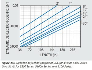
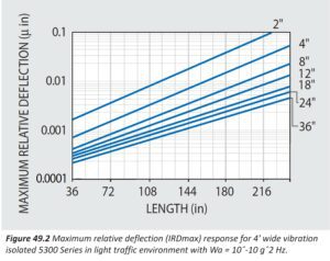
To aid you in the selection of optical tables for your application we provide you with manufacturing specifications in addition to real measured and verifiable static and dynamic table properties such as shown in Figures 47.1 to 49.2. However, for reference purposes and comparison to various manufacturers’ calculated table specifications, we want you to know that regardless of model or price category, the computed or predicted “Dynamic Deflection Coefficients” and “Maximum Relative Deflection”responses of KSI honeycomb tabletops are the lowest in the industry. These are presented in Figures 49.1 and 49.2 as discussed.
Theoretical Considerations in the Optical Table Relative Deflection Response Hypothesis
If we assume that the severity of laboratory floor vibration is statistical in nature and truly random, like white noise, then the rms (root mean square) relative deflection response RD of an idealized rigid lumped mass single degree-of-freedom system will be defined as follows 1 :
RD = (y-x) =
W a Q g 2 / 32 (pie symbol) 3 f n 3 ) 1/2 =
12.25 (W a Q / f n 3 ) 1/2 (8)
Where:
(Q / f n 3 ) 1/2 =
(DDC) = Dynamic Deflection
Coefficient of tabletop (9)
Q = Resonant transmissibility of table
W a = Floor Random Vibration Spectral Density,
(g 2 /Hz = floor mean squared vibration acceleration per 1 Hz band)
RD max = (nonisolated) maximum Relative Deflection of tabletop on rigid supports
Typical estimated random floor vibration conditions are:
Light traffic: W a = 10 -10 g 2 /Hz
Heavy Traffic: W a = 10 -9 g 2 /Hz
Light Manufacturing: W a = 10 -8 g 2 /Hz
Heavy Manufacturing: W a = 10 -7 g 2 /Hz
The Dynamic Deflection Coefficient (DDC) for 5300 Series Tables is derived from Equation (9) in conjunction with natural frequency and Q data contained in Figures 47.1 and 48.2, and plotted in Figure 49.1 for ready reference.
In vibration analysis it is reasonable to assume that an optical tabletop can be represented as a rigid mass-spring-and-damper single degree-of-freedom system up to its first resonance. Therefore, the above single degree-of-freedom Equation (8) is only applicable to a tabletop without isolation supports.
If isolators are added, the system has additional deflection coordinates or degrees-of-freedom and Equation (8) is not applicable. To resolve this in a simplified (quasi-theoretical) manner, Industry has proposed two correction factors and a modified interpretation of damping parameter Q . The correction factors are:
- Multiply Equation (8) by isolator transmissibility assumed as T = 1% at high frequency to, in effect, eliminate one degree-of-freedom.
- Multiply by 2 for an arbitrary worst case; and;
- Use the apparent Q from corner compliance tests used to derive Figure 49.2. We refer to the latter Q as apparent because it includes both rotation and translation response motions, instead of one degree-of-freedom as theoretically required. The resulting equation for Isolated Maximum Relative Deflection (IRD max ) for a vibration isolated tabletop is as follows:
IRD max = 12.25 (W a Q / f n 3 ) 1/2 x 0.02 (10)
The Maximum Relative Deflection of vibration isolated 5300 Series tabletops is derived from Equations (8) and (10) in conjunction with Figure 49.1 and is presented in Figure 49.2 for ready reference.
We’re here to help you select the right vibration-free optical table or workstation, or design a custom one that will meet your exact requirements. Click here to talk
Better built through better design to provide you with performance matched to your application
Whichever model you choose, our tables at Kinetic Systems are manufactured with the same precision tooling, and high-quality materials. The tables differ only in the amount of internal damping. We use a modern aerospace epoxy laminated steel-and-honeycomb structural sandwich beam design concept adapted to produce highly rigid optical tables and breadboards. The high stiffness and structurally efficient light weight of the honeycomb design makes it ideal for optical tables, resulting in a significantly high natural frequency (and therefore less vibration) than possible with the same size solid granite or ribbed cast iron designs. All our standard honeycomb optical tables have ferromagnetic stainless steel top skins; carbon steel bottom skins and sides; a high shear modulus, corrosion-resisting, plated steel, hexagon cell honeycomb core; and a proprietary damped epoxy formulation. We manufacture our own precision honeycomb core. For added stiffness and damping, we add steel C-channels treated with a damped laminate to form the side and end panels of each table.
Epoxy-lamination is performed under pressure with the top skin against a precision master tool plate. When the epoxy cures, the precision flatness of the master tool plate is effectively “frozen” and transferred to the top skin, or working surface, of the honeycomb optical table or breadboard.
Each top skin can receive mounting holes over the entire tabletop on a grid pattern of 1″ or 25mm spacing. Prior to assembly, topskins are drilled and tapped using our custom designed CNC drilling machines. After all chips are removed, the top skin and SPILLPRUF core are completely cleaned using a high pressure, high temperature, neutral detergent spray thus assuring a chip-free tabletop.
Finally, the steel side and end panels are mechanically attached using a proprietary method to the top and bottom skins for increased strength. The top surface is lightly sanded to provide a smooth, non-reflective finish and the sides are laminated with a scratch resistant, high pressure, granite-look laminate trim. The bottom surface is treated with a scratch-resistant, non-reflective black polyurethane finish. Before shipment, tables are checked for dynamic compliance, natural frequency, damping, and flatness.
Performance Specifications
| For Typical 4’ x 8’ x 12″ Table | |||||
| 5300 | 5200 | 5100T | 5100H | 5100 | |
| Flatness (overall) | ± 0.005″ | ± 0.005″ | ± 0.005″ | ± 0.005″ | ± 0.005″ |
| Damped natural frequency | 220 Hz | 230 Hz | 245 Hz | 270 Hz | 250 Hz |
| First resonance transmissibility Q | 2 to 6 | 6 to 9 | 9 to 13 | 13 to 18 | 15 to 20 |
| Deflection
under 250 lb concentrated load at center |
£ 7.0 (10) -5in. | £ 7.0 (10) -5in. | £ 7.0 (10) -5 in. | £ 7.0 (10) -5 in. | £ 9.5 (10) -5 in. |
| First resonance corner compliance | 1.8 m in/lb | 5 m in/lb | 8 m in/lb | 25 m in/lb | 25 m in/lb |
| Max. dynamic deflection coefficient | £ 0.3 (10) -3in. | £ 0.5 (10) -3in. | £ 0.6 (10) -3 in. | £ 0.7 (10) -3 in. | £ 0.9 (10) -3 in. |
| Max. isolated relative motion* | £ 0.8 (10) -9in. | £ 1.3 (10) -9in. | £ 1.5 (10) -9 in. | £ 1.9 (10) -9 in. | £ 2.4 (10) -9 in. |
| Core shear modules | 225,000 psi | 225,000 psi | 225,000 psi | 225,000 psi | 225,000 psi |
| *Performance with isolation under a light traffic random floor vibration condition of W Q =10 -10 g 2 /Hz | |||||
FEATURES
All KSI Tables Feature:
- SPILLPRUF™ Spill Management System
- High-Efficiency Broadband Damping
- Plated Steel Precision formed Honeycomb Core
- Low Reflective Surfaces
| 5300 | 5200 | 5100T | 5100H | 5100 | |
| Quad-Tuned Damping | YES | NO | NO | NO | NO |
| Tuned Damping | YES | YES | YES | NO | NO |
| Broadband Damping | YES | YES | YES | YES | YES |
| Ferromagnetic Stainless Steel Top Skin | 3/16″ Thick | 3/16″ Thick | 3/16″ Thick | 3/16″ Thick | 1/8″ Thick |
| Carbon Steel Bottom Skin, Black Polyurethane Finish | 3/16″ Thick | 3/16″ Thick | 3/16″ Thick | 3/16″ Thick | 1/8″ Thick |
| Plated Steel, Precision Formed Honeycomb Core | YES | YES | YES | YES | YES |
| Maximum Length* | 20’ | 20’ | 20’ | 20’ | 12’ |
| Maximum Width | 6’ | 6’ | 6’ | 6’ | 4’ |
| Maximum Thickness | 36″ | 36″ | 36″ | 36″ | 12″ |
| *Tables longer than 16’ are custom. | |||||
KSI Optical Table Damping Options
Quad-Tuned Damping
Our Ultimate Performance 5300 Series tables use “quad-tuned” damping in addition to the broadband damping of the epoxy. This method utilizes individually tuned absorbers embedded in all four corners of the table, tuned to the lowest two natural frequencies (bending and torsion) of each optical table. This is narrow band selective damping, provided by four frequency-tuned, mass-spring resonators dry-damped and tuned to resonant response, 180° out of phase, with the lowest natural mode frequency of the table. The out-of-phase inertial forces induced in each resonator mass acts to cancel or “absorb” the motion of the table at its natural frequency. 2“These tuned absorbers provide uniform damping performance over a broad temperature range. Competitive damping using “lossy” materials is temperature sensitive and can vary widely, particularly at lower than normal temperatures.”Tuned Damping
Our Superior Performance 5200 and 5100T Series tables feature the same construction as our 5300 Series tables except they use tuned absorbers embedded in the table. Further damping is provided by the energy-dissipating properties of our proprietary epoxy used in the table construction.
Broadband Damping
Our two economy models, the 5100H and the 5100 Series, are simply damped by the energy dissipating properties of our proprietary epoxy formulation used in the table construction. The energy dissipation is achieved by a thick coating of epoxy covering 100% of the inside surfaces of the top and bottom skins of the table. This is referred to as “free layer” or “broadband” damping and is particularly effective at all high frequency resonances of the table.
The tables’ dynamic compliance, modal frequencies, and damping properties are obtained with state-of-the-art instrumented impulse force hammers, accelerometers, and an FFT (Fast Fourier Transform) program in a portable computer for storage and graphical presentation. 3

Flatness is measured with an electronic level with a resolution of ±1 arcsec or 4.8 microinches per inch. Flatness readings are computer-recorded along 8 lines comprising the perimeter of outside holes, principle diagonals and centerlines of the table, and then graphed in “Union Jack” format. Standard flatness for all tables is ±0.005 in. (±0.13mm) in the measured perimeter. Breadboard flatness is ±0.004 in. (±0.1mm) per 24 in. (610mm.)
For Special Requirements
Ask our applications engineers about the numerous available skin and core material options, including aluminum, nonmagnetic stainless steel and Invar. All KSI Optical Tabletops can be customized for length and width and can include special shapes, cutouts, and notches.
For more technical information, see Isolation Basics, Optical Tables 101, and VIBRAPLANE sections.
You can also contact us and our team of engineers will work with you to come up with the best solution to fit your needs.
2 DEN HARTOG, J.P. “Mechanical Vibrations,” Chapter 3, McGraw-Hill Book Co., 1956
3 HALVERSEN,W.G. and D.L. Brown, “Impulse Technique for Structural Frequency Response Testing”, Sound and Vibration, November, 1977
Protecting an optical table’s inner core from spills due to water-cooled or liquid-dye lasers, coffee, and soft drinks prevents major contamination deep in the honeycomb core and ultimately the stability of the table.
The SPILLPRUF™ configuration seals off entire rows of mounting holes and channels liquids safely away from the table’s internal honeycomb core. Unlike tables with individually sealed holes that must be painstakingly vacuumed one by one to clean up spills, SPILLPRUF provides the ultimate level of honeycomb protection by sealing entire rows of holes. Cleanup is easier, faster, more efficient and doesn’t require the removal of apparatus from the table.

SPILLPRUF increases table rigidity
The SPILLPRUF all-metal construction provides a truss-like reinforced double top skin that increases the stiffness of the table. KSI uses the same principle used to increase stiffness in aircraft wings.
Some alternative designs use a low modulus plastic dimpled membrane in series between the skin and core. This effectively reduces table stiffness.
Metal cup designs add weight and therefore increase deflection but do not stiffen the table.
SPILLPRUF maintains table thermal conductivity
Our SPILLPRUF all-metal construction ensures rapid heat flow throughout, eliminating tabletop distortion due to uneven expansion and contraction. Alternative designs using a plastic membrane under the top skin will experience slower heat transfer and flatness degradation.
SPILLPRUF – A Better Technology For Handling Spills
The patented SPILLPRUF technique for protecting the inner core of KSI’s honeycomb optical tables from spills is a unique feature that also solves a problem many customers have had with individually sealed holes.
Spilled liquids are never confined to one hole, they always drain into many holes over a random area. With the individually sealed holes approach, cleanup dictates that each hole be painstakingly vacuumed out, cleaned by pouring cleaning fluids into the holes, and then re-vacuumed to remove the cleaning fluids. Many times this process has to be repeated several times to assure proper cleaning. And if there is any apparatus on the table it would need to be removed to allow access to holes.
With the SPILLPRUF design, fluids drain into an aluminum channel that isolates the spilled fluids from the honeycomb material. This channel not only completely isolates spills, but also helps to provide additional damping and structural integrity to the tabletop. Cleanup is simply accomplished by tilting the isolated tabletop (pneumatic leveling valves allow for this process), inserting a vacuum nozzle in each of the lowest rows of holes, and removing the spilled fluids and cleaning solution. Because fluids are drained to the lowest hole in each row, there is no need to remove any apparatus from the tabletop to facilitate cleaning.
SPILLPRUF U.S. Patent #5,962,104